CFD-AR(T)
Augmented reality for visualization of CFD simulations
1 Introduction
Computational fluid dynamics (CFD) analyses systems involving fluid flows whit the help of computer-based simulations. It has a great impact on the industry targeting problems of design and optimization which may be related to environmental problems. Some Examples where CFD is being used are: investigating the impact of gas emissions, controlling combustion processes, and designing and optimizing offshore wind turbines and water systems. Presenting the results of complex systems simulations might be laborious work and this increases when presenting them to an inexperienced audience. This paper provides a method of visualization using augmented reality, which should simplify the process of analyzing CFD results.
2 Theoretical knowledge
This section covers the ground knowledge of fluid dynamics. A brief introduction to computational fluid dynamics CFD and augmented reality is also covered.
2.1 Fluid dynamics
Fluid mechanics deals with the physics of liquids and gases. In order to better describe the physics of liquids and gases a mathematical model of these has been developed. This model describes liquids and gases as a continuum which is called fluid [1]. Fluid dynamics describes the flow of fluids, here is, for example, the velocity $u$ and pressure $p$ field of interest [2].
2.2 Governing equations
In fluid dynamics, the governing equation is a system of partial differential equations called the Navier-Stokes equation. This system of equations describes the behavior of fluids [2]. In this paper, only the equation for incompressible (density $\rho$ is constant) fluids would be covered.
\begin{equation}
\nabla \cdot u = 0
\end{equation}
\begin{equation}
\rho \frac{Du}{Dt} = - \nabla p + \mu \nabla^2 u + \rho f
\end{equation}
The first equation is called the Continuity equation. This balance equation states the principle of conservation of mass, i.e. mass can neither be created nor destroyed [1]; Thus the right-hand side of the equation is equal to zero.
The second equation is called the Momentum equation. This balance equation describes the principle of conservation of momentum, i.e. Newton's second law [3]. In the left-hand side of the equation the term $\rho \frac{Du}{Dt} = \rho(\frac{du}{dt}+u\nabla u)$ describes the total derivative of the velocity $u$, i.e. the change of velocity with respect to time and a convective term (local changes in the velocity $u$) [1]. On the right-hand side the term $- \nabla p$ describes changes in pressure, i.e. pressure forces. Secondly, a diffusion term $\mu \nabla^2 u$ describes viscous forces in the fluid [3]. the last term of the right-hand side $\rho f$ describes body forces.
2.3 Augmented reality
Augmented reality (AR) is one of the emerging technologies of the last years; with the help of augmented reality digital elements are placed over the „real world“, merging the „real world“ with a digital extension. It differentiates itself from virtual reality (VR) since VR is an isolated experience from the „real world“.
There exist two types of augmented reality: marker-based and marker-less. This paper will only cover marker-based AR. Marker-based AR reference objects are needed to place the digital objects, for this, image recognition is used; with the help of a camera, the AR implementation will recognize patterns, colors, and characteristic features. It will later compare the detected object with its information bank. Once a match has been found, it uses algorithms to determine the pose and place the digital object in the right spot [6].
2.4 Computational fluid dynamics
Since the governing equations are complex and non-linear, an analytical solution is only possible for certain cases. In general, for complex domains (the geometry of the region of interest) numerical algorithms are needed. These algorithms approximate the solution via iterative methods [3]. For doing this a discretization of the domain and time is needed, this helps to simplify the computation of the equations. By the discretization of the domain, the domain is divided into smaller elements where solutions of the governing equations are known or easy to compute. The discretization of time, time is as small intervals, in each of these intervals a new solution to the equations is computed.
Process
The process of CFD simulations is divided into three main elements: pre-processor, solver, and post-processor[3].
pre-processor
In this Stage the domain of interest is defined, for 3D complex structures this is done via CAD (computer-aided design). This domain is then divided into smaller, non-overlapping subdomains. These elements consist normally of cells or control volumes. The set of elements is called a grid or mesh. After defining the mesh the physical (e.g. incompressible fluid) and chemical phenomena as well as the fluid properties need to be defined. Some of the fluid properties are velocity, pressure, temperature, etc. Another important task in this stage is the definition of boundary conditions.
solver
In this stage, a variety of numerical solution techniques are implemented. In CFD the finite volume method (FVM) has gained popularity, this numerical algorithm consists of three main steps. The first step is the integration of the governing equation over all the control volumes f the domain. This step expresses the conservation of properties for each element, this distinguishes the finite volume method from other CFD techniques. These integral equations are then expressed into a system of algebraic equations, this system of equations is suitable for computer solution techniques. The solution of this system of equations is then solved via an iterative method [3].
post-processor
This stage deals with the visualization of the results. Here, graphic outputs are generated such as 2D and 3D surface plots, vector plots, domain and mesh display, particle tracking, etc [3].
2.5 Hardware requirements
For complex CFD cases, e.g. with a high number of cells, a big computational power is needed. For this purpose, computer clusters are used. A cluster is a set of connected computers, where each individual computer is referred to as a node [4]. Combining computers a higher computational power is achieved. For this to work smoothly special hardware and software are needed. On one side, for high-performance computing (HPC) supercomputers are normally used. On the other side, software with implemented parallel computer architecture is used [5].
3 Implementation
For the implementation, a basic CFD case was computed: a flow around a sphere. The computation was achieved mostly with open-source software.
3.1 Meshing
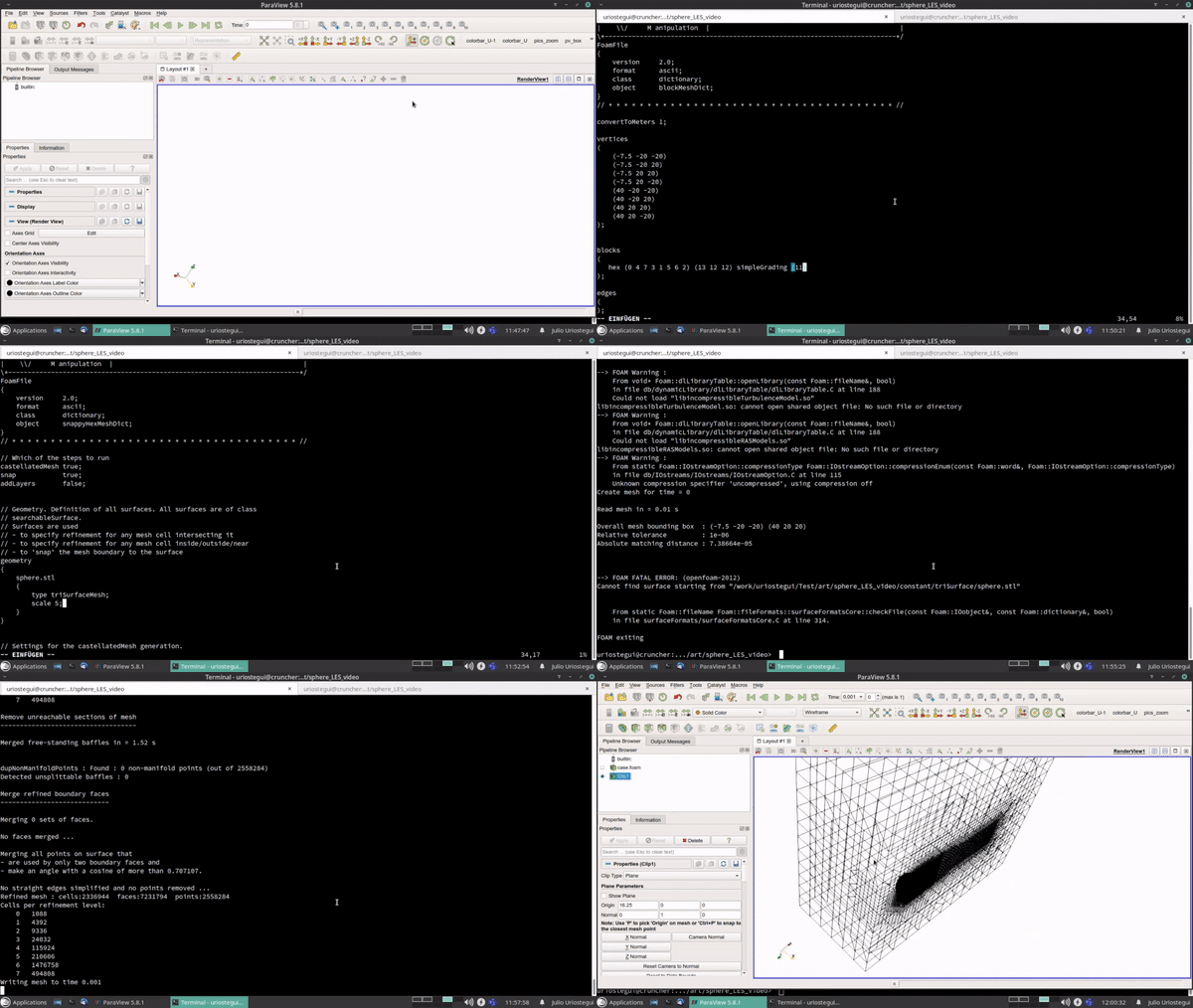
For the Meshing with Gmsh and the meshing solution of OpenFoam. First, the geometry of interest (in this case a sphere) was created whit Gmsh. The meshing process of the sphere was also done with Gmsh. The domain where the sphere „lives“ is a box; inside this box, the solution for the governing equations will be computed. This box was created and meshed with OpenFoam. After that, both elements were placed together. To achieve a high definition in the solution, the size of the elements behind the sphere was decreased.
3.2 Parametric definition and CFD-solver
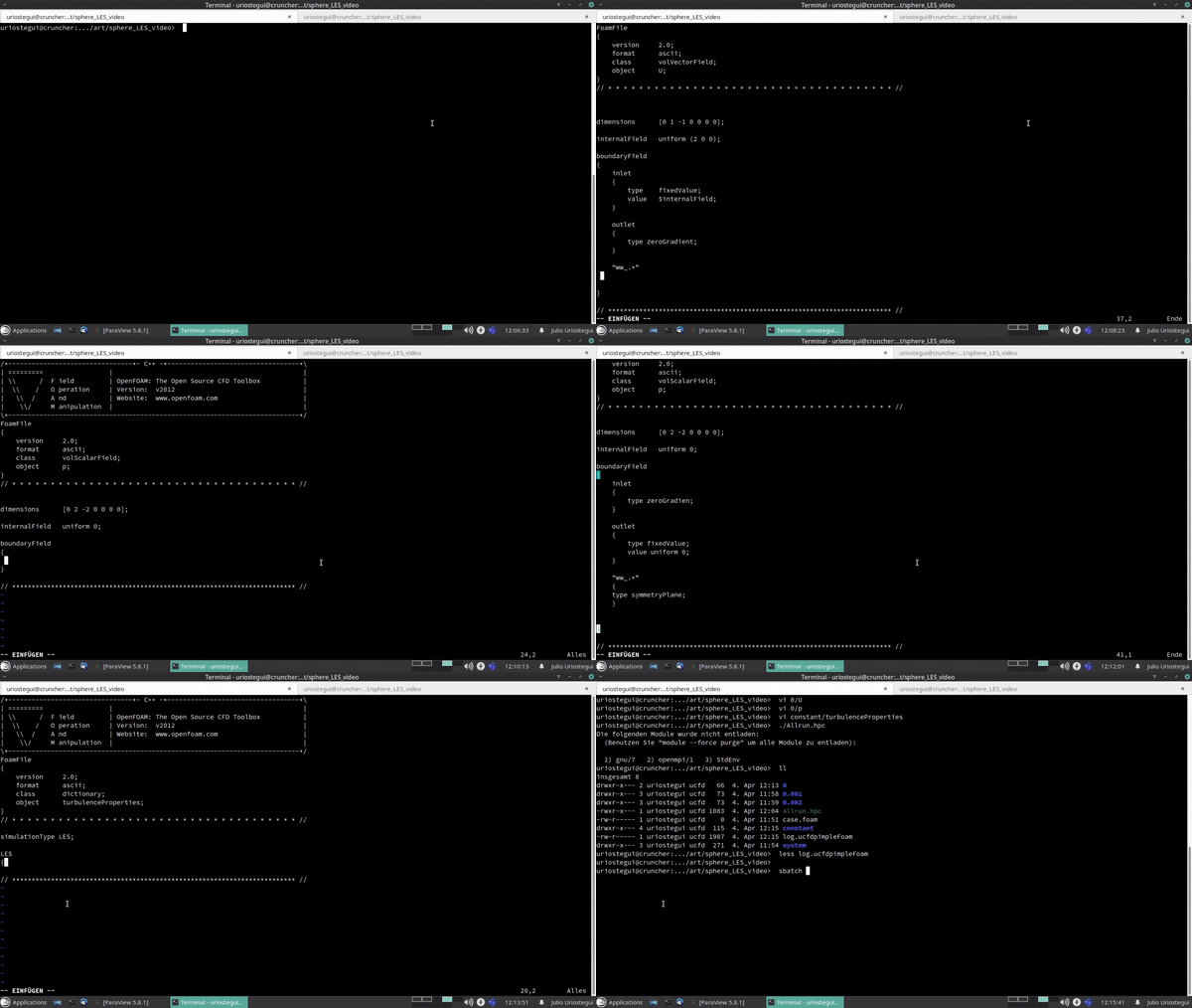
This part of the process was made with OpenFoam. First, the parameters and boundary conditions were defined. The physical properties were also defined in this stage. For solving this case the simulation was run on 64 cores. The total time of the simulation was 10 hours.
Post-processing
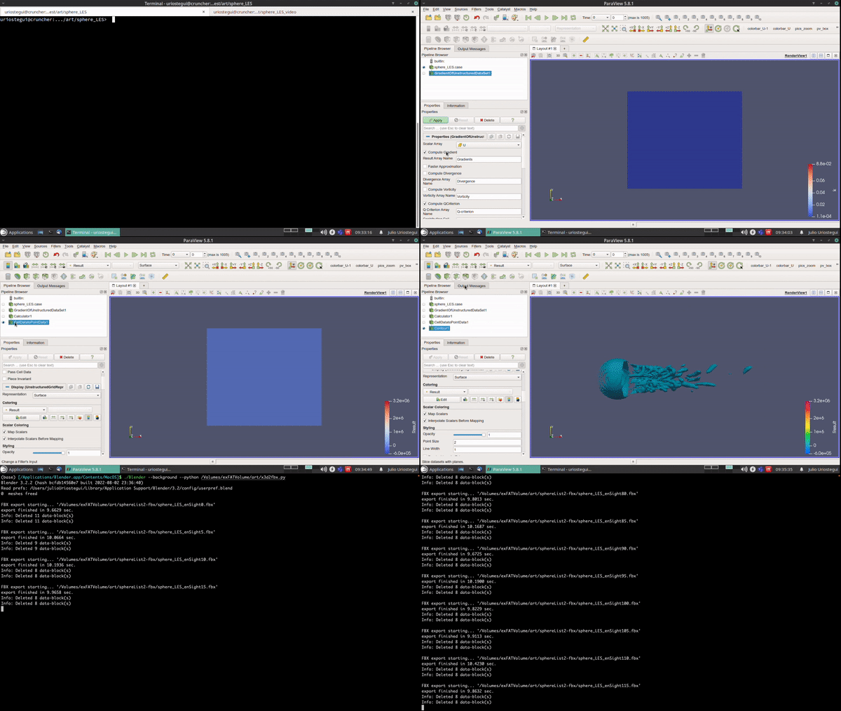
The post-processing was done with ParaView. Here, plots of the q-criterion were created. The q-criterion. These plots show the vortex structures in the fluid. For coloring these structures the values of $\frac{dz}{dy}$ were used.

3.3 AR implementation
For the augmented reality a reference object and the CFD sequence are needed. The reference object was created with the help of Fusion360, the idea was to create a sphere illustrating the mesh used in the CFD process. After that, the model was 3D printed and mounted in a base. The augmented reality application was created with Unity. Before working with Unity the CFD files' format needed to be converted with Blender. Following that, the reference object and the CFD sequence were merged in unity.
4 Conclusion
After showing the augmented reality implementation to an inexperienced audience, a great interest from the audience towards fluid dynamics, CFD, and the resulting simulation was shown. This proved that this method improves the presentation of results, simplifying the understanding of the results for inexperienced audiences. As for the process presented in this paper, improvements in the importing and exporting of files might be done; since the software used in this process support different formats.
References
[1] H. Schade, E. Kunz, F. Kameier, and C. Paschereit. Str ̈omungslehre. 4th ed. de Gruyter,
2013.
[2] Roger K. Smith. Introductory lectures on fluid dynamics. 2008.
[3] H. K. Versteeg and W. Malalasekera. An introduction to computational fluid dynamics.
2nd ed. Pearson, 2007.
[4] Computer Cluster. URL: https://dynamics.microsoft.com/en-us/mixed-reality/guides/what-is-augmented-reality-ar/.
[5] Introduction to Parallel Computing. 2021. URL: https://www.geeksforgeeks.org/
introduction-to-parallel-computing/.
[6] What is augmented reality or AR? URL: https://dynamics.microsoft.com/en-us/mixed-reality/guides/what-is-augmented-reality-ar/.


